> Energy band gap>
GaAs |
AlxGa1-xAs |
InxGa1-xAs
> Refractive index
> GaAs |
AlAs |
AlxGa1-xAs |
InxGa1-xAs
> Devices
> Bragg mirror |
SAM |
RSAM |
SA |
SANOS |
SOC |
Microchip |
PCA
> Device application
> Papers |
Patents |
FAQs
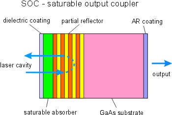
SOC - Saturable Output Coupler
SOC construction and application
Construction:
- The SOC consists of a partial mirror and a saturable absorber.
- The single crystalline layers of the mirror and the absorber are grown on an undoped GaAs wafer.
Application:
- Using a saturable output coupler (SOC), a self-starting, passively mode-locked diode pumped solid-state laser with a very simple layout can be arranged.
- In case of using a SOC instead of a SAM for passive mode-locking the optical pump power can be provided through a dichroitic end mirror of the laser cavity.
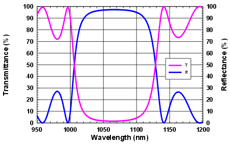
• Transmittance
Transmittance
- The transmittance of the saturable output coupler is mainly governed by the reflectance of the partial reflector and the absorptance of the absorber layer.
- The number of film pairs in the quarter-wave stack of the AlAs/GaAs partial reflector (Bragg-mirror) determines the reflectance.
- It follows from the energy conservation law T + R + A = 1 (T - transmittance, R -reflectance, A - absorptance), that the transmittance is given by T = 1 - R - A.
- The reflectance of the Bragg mirror increases with increasing number of the high and low index film pairs.
- An AlAs/GaAs multilayer stack of 10 film pairs has at the design wavelength a reflectance of ~ 96 % and consequently a transmitttance of ~ 4%.
• Absorptance
Absorptance
The absorptance A of the SOC consists of two parts:
- saturable absorption As
- non-saturable absorption Ans.
The non-saturable part Ans of the absorption can be caused by macroscopic crystal defects with very short relaxation time.
The non-saturable absorption decreases with increasing relaxation time of the excited carriers in the absorber material.
In case of absorbers with a short relaxation time of ~ 1 ps the non-saturable part of the absorption can be
Ans ~ 0.2.A0.
The total absorption is the sum of both parts A1 = As + Ans.
The saturation of the absorption can be described with the following formula:
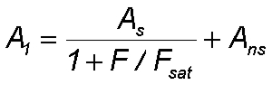
with
- A1 - Sum of saturable and non-saturable absorption
- As - saturable absorption
- Ans - non-saturable absorption
- F - radial dependent pulse fluence
- Fsat - saturation fluence of the absorber.
The pulse fluence F depends on the beam radius r for a Gaussian pulse as follows:
with
- F(r) radial dependent pulse fluence
- F0 - maximum fluence on the beam axis
- r0 - Gaussian beam radius
Both the fluence and the saturation depend on the beam radius r. To get the effective absorption A for the pulse an averaging over the whole illuminated area on the absorber is needed.
The figure shows the saturation behaviour according to the formulas above for A1 and the averaged absorption A with a
certain value of non-saturable absorption Ans = 0.2 A0.
The absorption values As and Ans are normalized on a value A0 = As + Ans.
The averaging results in a lower saturation simulating an additional virtual non-saturable absorption.
Typical values of a saturable absorber mirror for mode-locking a solid state laser are:
A = 0.02 and Fsat = 70 µJ/cm2.
For mode-locking a fiber laser with more gain the absorption of teh SAm must be also larger:
A ~ 0.3, Fsat ~ 50 µJ/cm2.
The pule energy results from an integration of the radial dependent fluence as
With the laser repetition rate f the average laser output power Pav can be calculated as Pav = E.T.f
• Wavelength dependency
Wavelength dependency
The absorption increases with increasing photon energy, starting at the gap energy of the semiconductor material.
In case of a quantum well structure the absorption increases as a step-like dependency on the photon
energy due to the one-dimensional quantisation of free carriers.
Consequently, the reflectance versus wavelength curve of a SOC shows under
non-saturated conditions a decreasing reflectance for shorter wavelengths.